
Technical Guides
- Prepared by
- Canel Elektrik İnşaat
- Published
- Reading time
- 7 min
Hospital electrical infrastructure: critical loads, generator and UPS coordination, medical electrical safety, testing and handover, with the Haydarpaşa reference.
Electrical infrastructure in international hospital projects is designed to meet the safety and operational needs of different clinical areas, as well as the building’s overall energy demand. In operating theatres, intensive care units, interventional treatment areas and locations using life-support equipment, continuity of supply, protection against electric shock and fault management must be considered together.
One international reference for this approach is IEC 60364-7-710, which addresses electrical installations in medical locations. The UK National Health Service’s HTM 06-01 guidance also describes an engineering approach to the supply, distribution, safety and operation of electrical power in healthcare premises. These references place hospital electrical infrastructure within a lifecycle that includes design, verification, maintenance and operation, alongside installation. Applicable requirements must be established for the project and jurisdiction concerned.
1. Classifying critical loads and maintaining continuity of supply
Different hospital loads respond differently to a loss of power. General office loads and equipment that can directly affect patient safety or continuity of treatment should not be assessed as if they carry the same risks.
During design, loads are assessed according to their purpose, tolerance of interruption, required restoration time and the consequences of a fault. The appropriate supply architecture is then established.
Depending on the needs of the critical loads, the design may consider:
- A standby energy source alongside the normal mains supply.
- Generator supplies for the appropriate critical loads.
- Uninterruptible power supply (UPS) systems for equipment with very limited tolerance of interruption.
- Automatic transfer arrangements between normal and standby sources.
- Appropriate separation of critical and general loads across distribution boards and circuits.
These solutions are not applied in exactly the same way in every hospital. Supply architecture depends on medical-location classification, load analysis, risk assessment, applicable standards and project specifications. Standby sources, UPS systems and transfer arrangements must be selected to suit the identified need.
2. Coordinating generators, UPS systems and automatic transfer
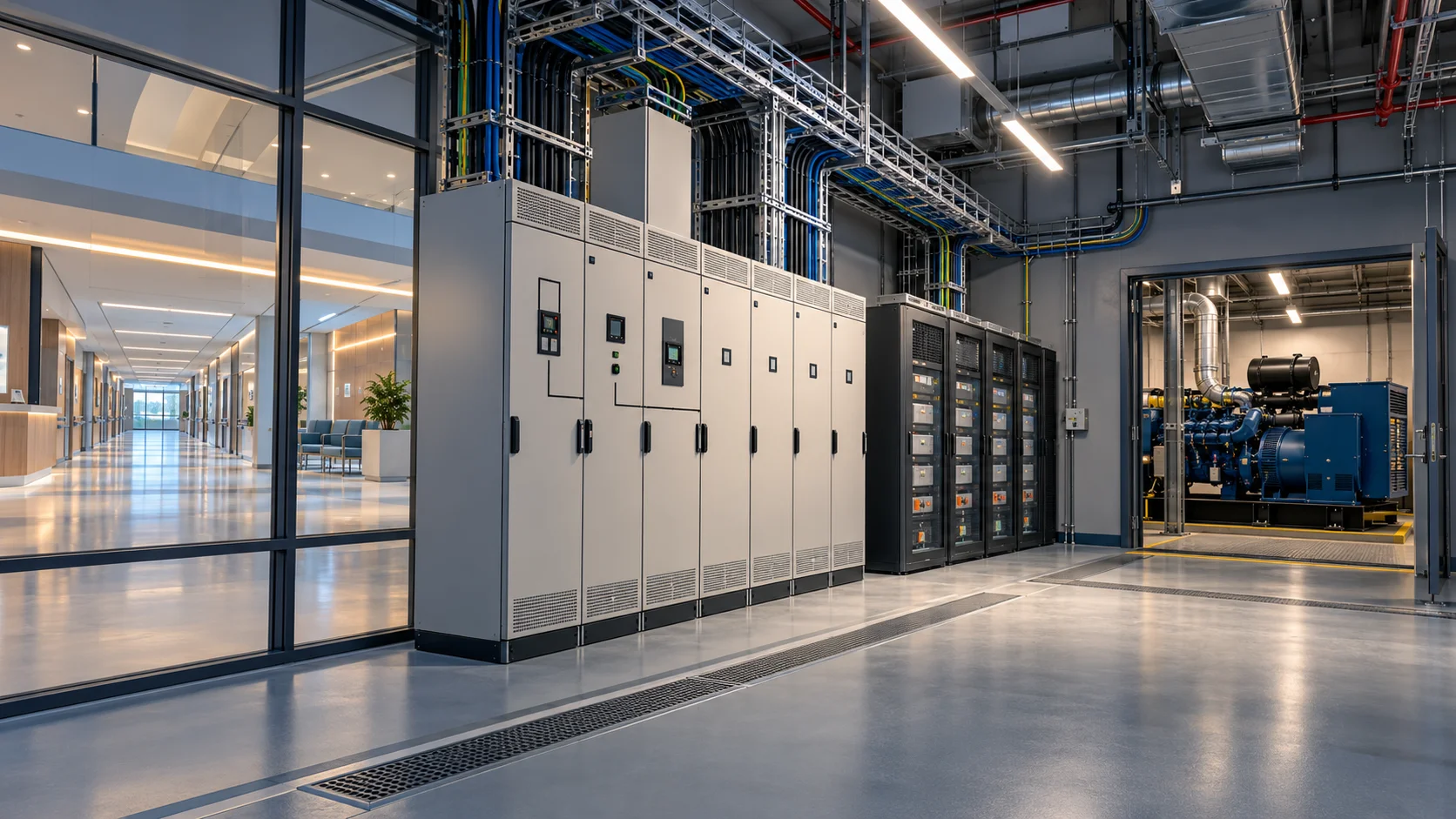
A standby generator alone does not eliminate every risk associated with power interruption. Generator starting time, the order in which loads are restored, starting currents and coordination with UPS systems must be considered together.
In an appropriate design, a UPS can supply critical equipment without interruption, or for a defined period, until the generator becomes available or the normal supply returns. UPS capacity and battery autonomy must be calculated using the connected load and required operating duration. A UPS does not, in every case, meet the need for extended standby power on its own.
Automatic transfer arrangements must monitor the normal source, check the availability of a suitable standby source and transfer loads according to the agreed sequence. Verification of generator operation under load, functional testing of transfer equipment and maintenance procedures also need to be considered when assessing reliability.
In electrical contracting, these systems should be treated as parts of the same power infrastructure. Panel connections, protective devices, cable sizes, load distribution and control wiring must be checked against the design and manufacturers’ documentation.
3. Medical electrical safety and equipotential bonding in operating theatres
Operating theatres and certain treatment areas require specific electrical safety assessment. A patient’s direct connection to medical equipment, conditions that affect body resistance and the consequences of power interruption can mean that these locations require different installation provisions from general areas.
IEC 60364-7-710 addresses matters including protection against electric shock, continuity of supply and supplementary equipotential bonding according to the use and risk classification of medical locations. Certain Group 2 medical locations may use medical IT systems and associated insulation monitoring, according to the design. These arrangements should follow the location’s classification and engineering design, rather than being applied indiscriminately throughout a hospital.
Equipotential bonding aims to reduce the risk of dangerous potential differences between conductive parts that can be touched simultaneously. Protective conductors, relevant metalwork, connection points and the electrical infrastructure of the medical location are therefore assessed against the project requirements.
Hospital electrical work consequently involves system selection, installation, measurement and verification as well as cable routing and equipment connections.
4. Distribution boards, cable routes and electromagnetic compatibility
Hospitals contain many electrical loads, communication systems, medical devices and mechanical services within the same building. Panel positions, circuit separation, cable routes and protective arrangements should therefore be determined through coordinated design.
Organising distribution by area of use, identifying critical supplies, providing safe access to boards and allowing for maintenance are significant design considerations. IEC 60364-7-710 includes provisions concerning distribution arrangements and electrical safety in medical locations.
Installation considerations include:
- Clear identification of boards and circuits.
- Cable sizes and overcurrent and short-circuit protection that match the design.
- Planning power, sensitive signal and communication routes with electromagnetic interaction in mind.
- Applying the relevant fire-stopping details at fire compartments and wall penetrations.
- Reviewing clashes between panels, cable trays, mechanical services and structural elements before site installation.
- Preparing current documentation that helps identify circuits during operation and maintenance.
These details support orderly installation and more controlled maintenance, fault finding and future system changes.
5. Fire detection, emergency lighting and safety systems
Hospital fire safety involves detection and warning infrastructure, emergency lighting, escape-route signs, relevant safety systems and, where required, coordination with other building services.
Fire detection design considers the purpose of each area, detection needs, detector locations, manual call points, audible and visual alarms and connections to the control panel. Design and installation must follow the applicable regulations and relevant standards.
Emergency lighting and escape-route signs support evacuation and safe movement when the normal supply fails. Their power sources, operating durations and test methods are determined through the relevant project specifications.
Before handover, the required checks may include connection inspections, functional tests, alarm scenarios and interfaces with other systems. Installation of the equipment alone does not complete this process.
6. Testing, commissioning and technical documentation
Completing hospital electrical infrastructure includes verification that systems operate in line with the design and relevant technical requirements.
Healthcare engineering guidance considers initial verification alongside safe operation and maintenance. Tests must be selected according to the system, design, manufacturer instructions and applicable requirements.
Depending on the contract scope, checks before handover may include:
- Visual inspection of wiring and connections.
- Protective-conductor continuity and earthing measurements.
- Insulation resistance and other relevant electrical tests.
- Distribution-board and protective-device checks.
- Functional tests of generators, UPS systems and automatic transfer arrangements.
- Relevant emergency-lighting and fire-detection tests.
- Review of identification, circuit schedules and current installation drawings.
- Preparation of test records and technical handover documents.
Early planning of testing and commissioning is particularly valuable on large hospital projects involving several contractors. Coordinated checks of electrical, mechanical and other technical systems help identify outstanding items and organise handover.
Why hospital project experience matters for Canel Elektrik
The Haydarpaşa Numune Hospital project provides a reference for reviewing Canel Elektrik’s electrical work in healthcare buildings. The low-voltage, low-current and lighting works in Canel’s project scope illustrate the importance of considering different infrastructure components together in a large hospital.
The wider engineering topics discussed above explain why hospital projects require a particular technical approach. They provide context for reviewing the scope and installation requirements of a reference; they do not state that every system described in this article was installed by Canel at Haydarpaşa Numune Hospital.
Canel Elektrik’s references in hospitals and pharmaceutical manufacturing facilities also show why electrical contracting must be considered against the technical needs of each building. Planning, site coordination, inspections and handover documentation should follow the agreed scope, applicable standards and the client’s technical specifications.